
by Jim Stewart, KC Micro Community Mentor
First of all, here’s a list of the parts we are using for our build. These instructions work for these parts. The instructions may not work for other parts.
- Transmitter - HobbyKing HK-T6A V2
- Receiver - HobbyKing HK-TR6A V2
- Servos - Hextronik HXT900
- Battery - Rhino 1750
- Motor - Towerpro 2408-21T-3A
- Electronic Speed Control - Hawking 20A or equivalent, 20 amp, 2 or 3 cell LiPo battery
- Battery Charger - IMAX B6AC+ Dual Power
Charging the Battery
The first step is configure the charger for the battery. Power up the charger and press the red button until the display indicates LiPo and then press enter.


Place the battery on a non-flammable surface. I like the small marble tiles available at Home Depot. Connect the battery to the charger using the big red and black leads for the power and the small 3-wire connector for the battery charging socket. Press start, confirm 3.9A charging current, press start again, confirm 7.4 volts. Press and hold start until charger beeps quickly. Press again to confirm. Battery should start charging.
Configuring the Receiver
Before we can configure the transmitter, we have to power up the receiver and servos. When the airplane is completed, the receiver and servos will be powered by the LiPo battery pack. For now, it’s much safer to power them up with 4 AA batteries in a Radio Shack battery box. These pictures show the wiring. You’ll have to find the connectors for yourself. I cut up an old CD-ROM audio cable to make mine.


From now on, any time I talk about where something is on the airplane, I will be looking at it from the back. In this case, the left servo is plugged into channel 1, the right servo into channel 2 and the battery pack into channel 3. The battery pack and the servos have to be plugged in exactly as shown. If you plug the connectors in backwards or some other way and you might destroy your receiver.
Next make sure the Bind jumper connector is installed in the BAT connector of the receiver.

Now we will power up the transmitter and receiver, bind them together and do some initial tests. Make sure there are eight fresh AA batteries in the transmitter and four fresh AA batteries in the Radio Shack battery box. Turn on the battery box, press and hold the Bind Range Test button on the transmitter, and then turn on the transmitter power. Hold the Bind Range test button for 10 seconds, then power down the transmitter and receiver. Remove the bind jumper and power up the transmitter and receiver. If the bind worked, you can now move the right and left servos by moving the right joystick right, left, up and down. Power down the receiver and move the right servo connector to the CH3 connector. Power up the receiver. You should be able to make the right servo move by moving the left joystick up and down. Power the receiver down and put the right servo connector back in CH2.
If everything tests out OK, we can now test the airplane with the flight battery and electronic speed control. Unplug the Radio Shack battery pack. Plug the Electronic Throttle Control (ETC) small cable into the receiver CH3. Be sure the wire colors line up like the picture below:

There should be no propeller on the airplane at this time. Check the transmitter and be sure the left joystick in in the full down position. Connect the LiPo battery. The ETC should beep loudly once. If it does, move the right joystick around and verify that the right and left servos move. Move the left joystick up slowly. The motor should start and run, with the speed controllable by the joystick. Slowly reduce the speed until the motor stops. Verify that the motor is running counter-clockwise as viewed from the rear of the airplane. If it is running clockwise you must reverse its direction. To do this, power everything down and disconnect any two of the three motor wires going to the ETX and interchange them. Verify that the motor is now turning counter-clockwise.
Configuring the Transmitter
The transmitter is presently configured to control a “normal” airplane, one with an elevator to control the pitch and ailerons to control turning. The Towel uses a different system, with two control surfaces serving as both elevator and ailerons. These surfaces are known as “elevons”. In order for the joystick to properly control the airplane, we have to configure the transmitter to “mix” the pitch and aileron signals from the right joystick and transmit the mixed signal to the airplane to control the elevons.
To configure the transmitter, we have to connect it to a computer and run a configuration program. I used the program Digital Radio available at http://www.sgr.info/usbradio/
Before we can run the Digital Radio program, we need a cable to connect the transmitter to the computer. There are several cables available, but I didn’t have one so I made my own. The cable I made connected the “Trainer” connector on the back of the transmitter with a serial port on my PC. The Trainer connector uses serial data, but is not RS-232 compatible. I made an adapter that converts the signals on the Trainer connector to RS-232 and then connected the RS-232 signals to a COMM port on my computer. Here’s a pinout of the Trainer connector:
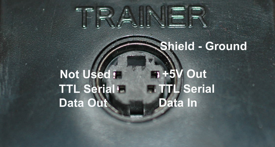
To make my cable, I used an old Apple mouse cable, a SchmartBoard RS-232 module, and a extension serial cable. I cut the mouse cable and stripped the end of it, connected the shield to GND on the ShmartBoard, connected +5V Out to +5V, TTL Serial Data In to TD, and Serial Data Out to RD. Then I connected the ShmartBoard DB-9 connector to the serial port on my computer.

Download digitalradio.zip and extract digitalradio.exe. Run it and you should get a display like this:

Click the Mix Data tab halfway down the menu. Set the Mix 1 and Mix 2 options as shown below:

Click the Main Data tab halfway down and set all the Normal/Reverse Channels to R. Set Switch A and B to Null.

Click Radio > Send Settings. Click Radio > Get Settings. The parameters you set should show in the Main Data and Mix Data menus.
Testing Transmitter Mix Settings
Power up the airplane. Move the right stick up. Facing each servo, the right servo should move counter-clockwise and the left servo clockwise. Move the right stick down. The right servo should move clockwise and the left servo counter-clockwise.
Move the right stick to the right. Both servos should move clockwise. Move the right stick to the left. Both servos should move counter-clockwise. This concludes wiring and testing your airplane.


